GM TPI and TBI cars and trucks use a 56 pin delphi connector assembly. (two actual connectors)
Racetronix and others sell a cheap connector soldered to a board which can be installed
in an old GM ECM case using a pair of standoffs. For the Megasquirt we have chosen the
Microsquirt MODULE for it's low cost and number of features. It is used in a number of commercial
PNP megasquirt ECU's.

The purpose of this project is a cheap plug and play Delph56 ECM that retains the factory ECM
case for a stock look, and is under $400.

EMISSIONS DISCLAIMER: Megasquirt does NOT have out of the box is Emissions logic built in. The Megasquirt
does NOT have a special system of beeping 'codes' to you if a fault exists. Such things must be programmed
using logical outputs or CAN.
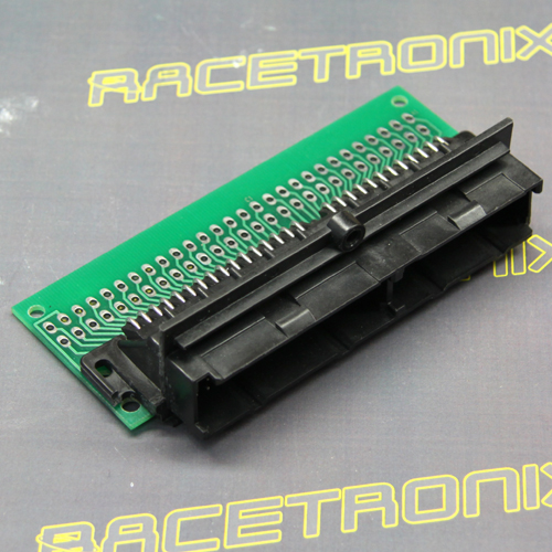
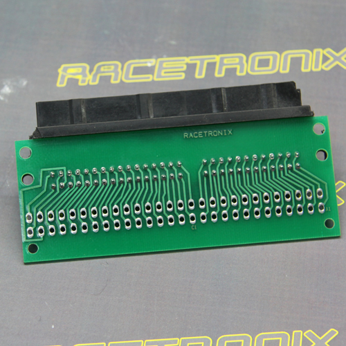
First we start with the Delphi 56 connector from Racetronix. Part # RHCA-001
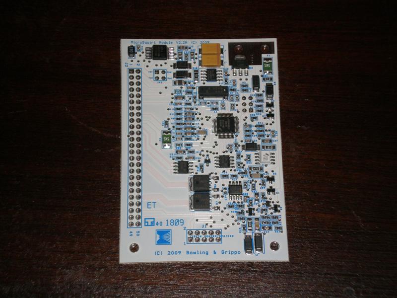
Next we purchase the Microsquirt Module http://www.microsquirtmodule.com/ from DiyAutotune.
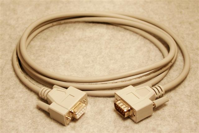
You will need a Tuner cable. Straight thru DB9
And a surface mount female DB9 connector.
Wiring a 4 wire GM Stepper IAC (Click here)
I purchased TWO microsquirt header kits, mainly because I wanted to use the standoffs in my '747 ECM case. You can also purchase the 4-40 x 7/16" standoffs on ebay and source screws locally.
The following chart is how you need to pin your Microsquirt 2.2 MODULE to the
reacetronix adapter board. This is based on a GM 1227165 ECM.

I used 22 awg wire for my jumpers. You will want to make sure your injectors, and grounds are 14 gauge.

The pins listed as "'165" are the Racetronix module side, and the pins listed as
"MS" are the Microsquirt J2 side.  The IAC pins come from your IAC board.


GM PIN   GM Circ Desc        		        MS DESC          MS PIN                   NOTES
----------------------------------------------------------------------------------------------------------------
A1  Fuel pump Relay GRN/WHT    			Fuel Pump        22                       Negative trigger
A2  AIR VALVE PORT SOLENOID BRN
A3  CANISTER PURGE GREN/YEL
A4  EGR SOLENOID  GRY
A5  SES LIGHT BRN/WHT
A6  IGNITION SWITCH  PNK/BLK             	Battery Power    1,2                      Splice to boath + IAC adapter
A7  TCC Lockup TAN/BLK
A8  ALDL Connector DATA orn/WHT
A9  ALDL Connector DIAG BLK
A10 VSS INPUT BRN
A11 MAF GROUND (TERMINAL B) BLK          	+5 Vref         15                       Provide +5v to MAP (SPLICE)
A12 SYSTEM GROUND  BLK                  	GROUND          37

B1  BATTERY always on ORN
B2  Fuel Pump Sense (CONTROL) TAN/WHT
B3  DIST REF LO BLK/RED          		IGN2 (SPARKB)   44	                       Coil #8 and #5 (purple and green)
B4  NOT USED
B5  Dist ref HI PURPLE/WHT       		WLED (SPARKC)   11                        Coil #7 and #4 (red and green)
B6  VATS (passkey sytem)
B7  ESC Module (knock) BLK               	Spare ADC 1     17                        Spare 0-5 volt ADC for knock read
B8  A/C INPUT Request GRN        		ALED (SPARKD)    7                        Coil #2 and #3 (red and blue)
B9  NOT USED
B10 PARK/NEUTRAL (Grounded in Drive)
B11 NOT USED
B12 MAF INPUT (Terminal C) DRK GRN          	MAP              3                        MAP sensor 0-5 volt ADC

C1  Cooling Fan Relay DK GRN/WHT               	FIDLE           20                        Fidle grounded output
C2  AIR VALVE CONVERTER SOLENOID BLK/PNK
C3  IDLE B LO    LT GRN/BLK                    	IAC 1B                                    Connect to IAC adapter module
C4  IDLE B HI    LT GRN/WHT                    	IAC 1A                                    Connect to IAC adapter module
C5  IDLE A HI    LT BLU/WHT                    	IAC 2A                                    Connect to IAC adapter module
C6  IDLE A LO    LT BLU/BLK                    	IAC 2B                                    Connect to IAC adapter module
C7  NOT USED
C8  4th gear switch                                                            Can be used with relay for TCC
C9  NOT USED
C10 Coolant Temp Sensor YEL              	Coolant          5                        Coolant temp 0-5v
C11 NOT USED
C12 Manifold Air Temp Sensor TAN         	MAT              9                        Manifold air temp 0-5v
C13 Throttle Position Sensor DK BLU        	TPS              13                       TPS signal 0-5v
C14 +5 VREF  GRY                        	+5 VREF          15                       Voltage for 5 volt sensors
C15 EGR Diagnostic switch DK GRN           	I used this for my boost control solenoid
C16 BATTERY always on ORN

D1  GROUND  BLK/WHT                         	Ground          35                        Engine block
D2  TPS,CTS, MAT Ground BLK             	Sensor ground   33                        Return ground for all 5v sensors
D3  SYSTEM GROUND BLK/WHT                   	Ground          39                        Engine block
D4  EST CONTROL WHITE  WHT              	OptoIn (-)      21                        Crank sensor signal. MUST use OptoIn -
D5  EST Bypass (TAN/BLK) TAN/BLK            	IGN1 (SPARKA)   48                        Coil #1 and #6 (purple and blue)
D6  o2 GROUND   TAN                     	Ground          41,43                     Engine Block
D7  o2 Sensor   PPL                     	o2              27                        Wideband preffered, 0-5v
D8  NOT USED
D9  NOT USED
D10 SYSTEM GROUND  BLK/WHT                  	Ground          49                        Engine Block
D11 A/C Pressure switch   DK BLU           	I used this for spareADC2 for my second map sensor
D12 MAF Burn Off Relay BLK       		Tach            29                        Connect to tach wire
D13 NOT USED
D14 NOT USED
D15 Injectors 1,3,5,7 LT BLU               	INJ1            24,26,28,30,32            Injector Driver #1
D16 Injectors 2,4,6,8 LT GRN               	INJ2            34,36,3,40,42             Injector Driver #2

Brown wires from each coil MUST ground to cylinder head.
Power wires from each coil MUST go to ignition power.

WLED and ALED need a 1k resistor between the pin and vref to pull up the signal.
Pin 19 needs to splice to vref to pull up the signal for the crank trigger. The Microsquirt Module has an Opto filter so no resistor
is needed.

I know the Sloppy mechanics guys use VR1 for the crank trigger on a Microsquirt, but the Microsquirt MODULE is different and you
cannot use a hall effect trigger in the VR input (pin 23). So you MUST use pin 21 (OptoIn -). Then you connect 5v from vref through
to pin 19 (OptoIn +).

58x wheels are also known as 60-2 because it's a 60 tooth wheel missing 2 teeth. Each tooth is 6 degrees. Tooth #1 should be 78* BTDC.


Tunerstudio ignition settings:

Spark mode = Toothed wheel
Ignition input capture: Falling edge
Spark output: Going High
Number of coils = Wasted Spark
Trigger wheel arrangement = Single wheel
Trigger wheel teeth = 60
Missing teeth = 2
Tooth #1 angle = 78 (Check with a timing light, but 78 degrees was dead on for my 2009 LC9)
Main wheel speed = Crank wheel


MAP SENSOR:


Unplug both MAF relays and discard.

Remove the MAF plug, and replace it with a MAP sensor plug wiring as follows:

MAF PIN C -----> MAP PIN B (SENSOR OUTPUT)
MAF PIN B -----> MAP PIN C (+5 vref)
MAF PIN A -----> MAP PIN A*

MAF PIN A could potentially pick up electrical noise since it is a common ground to D1. You could instead splice
MAP PIN A to the sensor ground (D2) leading to the TPS.  Do NOT try to do this in the ECM case, as MAF PIN A is spliced
to D1 in the wire loom.


Fuel pump control is NEGATIVE, not POSITIVE like GM. A second relay MUST be added, or you need to redo
the wiring in the harness.

I used a small 40 amp relay found in any auto parts store and stuck it inside
the ECM case, but later moved it external bypassing the fuel pump / oil pressure circuit.

Here is how I wired mine:

30 to Battery (B1 on D56 connector)
87 to FACTORY Fuel Pump relay (A1 on D56 connector)
86 to swiched ignition (A6 on D56 connector)
85 to pin 22 on microsquirt


If you have done it properly, on power up, the MS will engergize the relay for
5 seconds. So you will hear CLICK count to 5, CLICK again. This will give you
the +12 volts you need on pin A1.


Other optional features you may need:


Pin 20 in the above chart is used for your cooling fan. It has the same logical control
as pin 7 or 11, but can also output a frequency. You can use it for the cooling fan, or some other purpose.

Pin 16 is an ADC channel, which takes in a +5 signal. It can be used for a voltage MAF or
any other device that gives a 0-5 volt signal. (VSS, GPS, whatever). I used this for my second map sensor.

Pin 17 is another ADC channel. The chart above uses it for Knock sensor control. It can be
used for any purpose that checks a +5 input just like pin 16. I'm using it for my fuel pressure sensor.


EXTRA PINS:

Pin 10 is CAN H, and pin 12 is CAN L. These are used to communicate with other devices
(Such as a transmission controller, heads up display, etc) using the CAN BUS protocol.
If you would like to use these, extend them to some free pins on the D56 connector.

Pin 18 is for a FLEX FUEL sensor. Can be used for Nitrous control, Launch control.


J1 Pin1 - PA0 Can be used for boost control, launch control, I/O extension. If you are interestd in using it,
you need to make a small boost control circuit.  I'm using it for electronic boost control.

J1 Pin2 - PE1 Table switching. Can be used for manually selecting between street / race /
valet tunes.
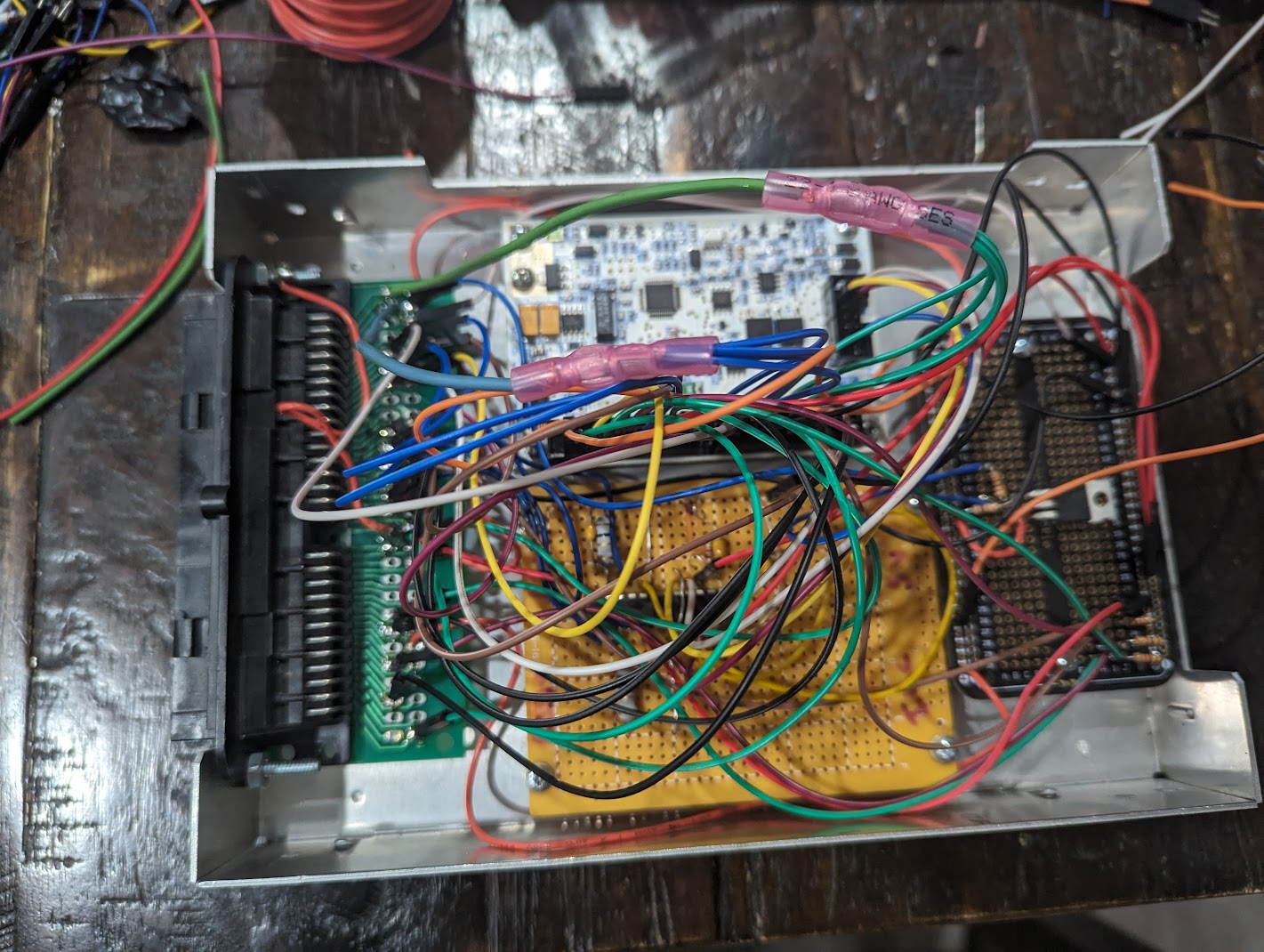
On the above picture, the yellow board is the IAC circuit.

On my car I chose NOT to run a relay inside the case (after running one for ten years) and instead decided
to change the factory relay wiring to be a ground-initiated.

The small board on the right is my boost control circuit.
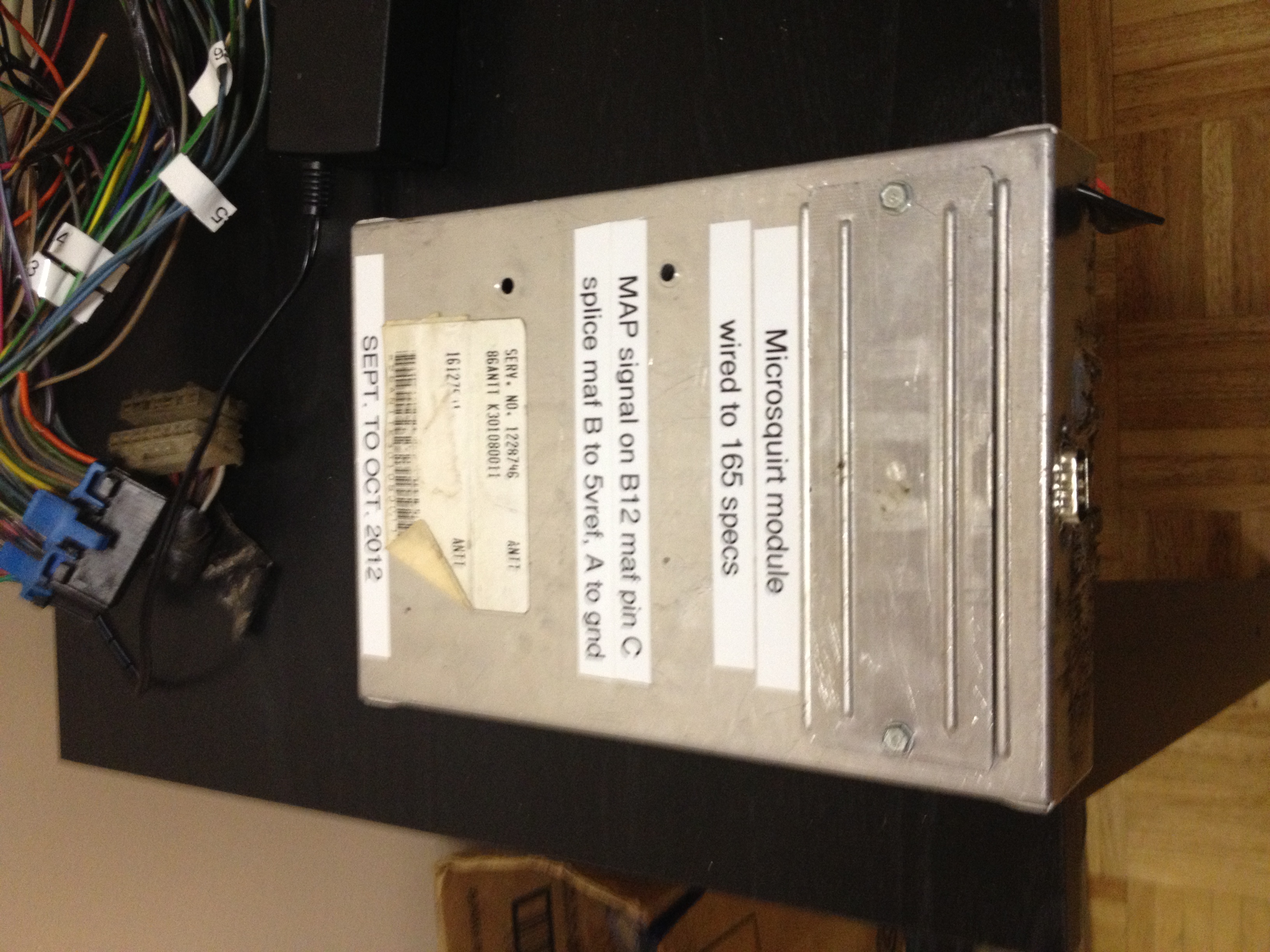
Complete closed case with serial port:
Once you have completed assembling the board, you will need to upload the firmware
over your serial cable. This is very simple.

*** MAKE SURE YOU USE MS2EXTRA CODE ***

1) Download either pre-compiled firmwhare, or compile your own ms extra _us.s19 file
2) Run the MS firmware utility 'ms2loader_win32.exe'
3) Select 'Microsquirt', and your comm port settings
4) Ground pin 8 on the Microsquirt and power up the unit. (bootjumper)
5) Follow the on screen directions.


Once firmware is uploaded, power down the unit and remove the ground from pin 8.
The latest firmware can be found here
You are now ready to open Tunerstudio and tune.
Boost control circuit you might want
Wiring docs and schematics you might want